Get in touch

Leave your details below and one of our specialists will be in touch as soon as possible.

Disa pneumatic blast pot: reduced abrasive consumption, increased productivity, lower clean-up costs.

Disa pneumatic continuous pressure blast pot is controlled by components such as PLC, level gauge and differential pressure gauge. It can realize the functions of automatic shot feeding and continuous shot blasting without stopping the blasting process to refill the pressure tank with abrasives. This ensures the continuity and effectiveness of shot peening strengthening work, and meets the requirements of automated assembly line operations.

Features and benefits of Disa pneumatic sandblasting pot:

disa-blasting-pot
Control box SP 147
X
Control box SP 147 
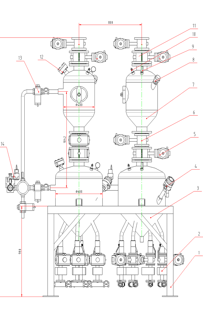
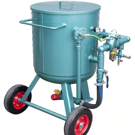
The blast pot is designed to be swiftly deactivated, thus ensuring enhanced safety.
SU 034 Bleed Valve
X
onluchtkraan 
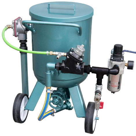
To put the blast pot into operation, the Bleed valve must be closed by applying control pressure to the membrane. The air valve is open if we have no control pressure on the membrane, in other words, we speak here of a normally open air valve.
Filling cone SP 014CE
X
disa-vulklep 
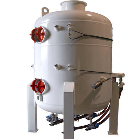
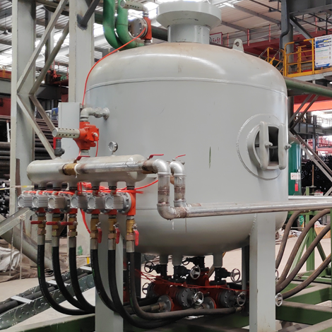
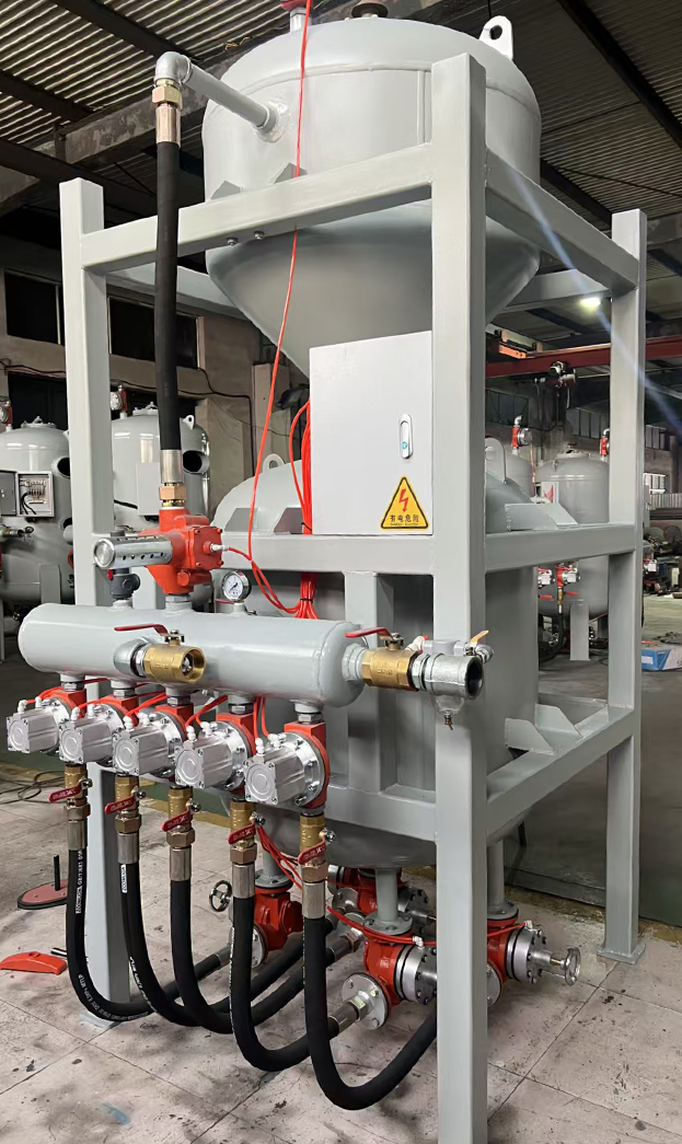
The compressed air enters the vessel through the main air valve through the riser pipe. The filling cone SP-014 is pressed upwards into the rubber collar ring by this compressed air flow. The blast pot now forms a closed vessel and is presurised
SU098 Main air valve
X
hoofdluchtkraan_dicht 
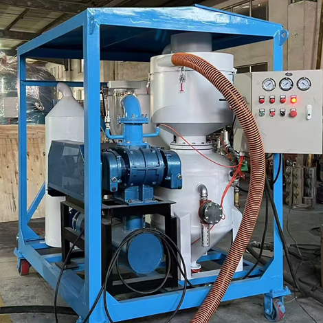
To start up the blast pot, open the main air valve by applying pilot pressure below the piston. The air valve is closed if we have no control pressure below the piston, in other words, we speak here of a normally closed air valve.
SU 012 Grit cylinder
X
gritcilinder_dicht With the aid of the grit cylinder it is possible to have a set amount of blasting media dispensed through the grit valve housing. In the grit valve housing there is a spring which in the rest position always ensures that the piston rod with the rubber cone on it, starts in its outward stroke. In this rest position, the blasting medium flow in the grit tap housing is closed.

Product details

The abrasive blast pot is mounted directly beneath the abrasive storage hopper for gravity-fed operation. The covered hopper lifting tube assembly filters abrasives through the perforated baffle plate and effectively contains abrasive spillage during pot de-pressurization, preventing buildup in the work area.


Technical data:

disa-blast-pot disa-blast-pot

Innovative design

1.Lower pot bracket
2. Outlet valve combination     
3. 600 pot body
4. Radio frequency admittance level meter
5. DN125 Pneumatic butterfly valve DN125
6. Pneumatic pinch valve
7. 400 pot body
8. Rotary paddle level indicator
9. Ordinary pointer pressure gauge
10. Safety valve
11. Pneumatic pinch valve
12. Exhaust valve
13. Inlet air system for upper and lower pots
14. Total inlet air system

1.Lower pot bracket: Bears the weight of the entire tank body, welded by section steel.
2.KL Valve Assembly (see figure)
3.600 Tank Body: Main cylinder for shot blasting, with a volume of 0.1 m³.
4.RF Admittance Level Gauge: Detects the lower limit of shot remaining in the tank. When the shot reserve is insufficient, the level gauge sends a signal to the PLC, which then initiates the shot feeding program.
5.Pneumatic Pinch Valve: Automatically controls valve opening and closing, with excellent sealing performance when closed.
6.400 Tank Body: Shot feeding tank for shot blasting, with a volume of 0.06 m³.
7.Rotary Paddle Level Switch: When the shot volume in the 400 tank reaches the sufficient level, the level switch sends a signal to the PLC, which then stops the shot feeding program.
8.Analog Pressure Gauge: Displays the real-time pressure in the tank or pipeline.
10.Safety Valve: When the real-time pressure in the tank or pipeline exceeds the designed maximum pressure, the safety valve opens to forcibly discharge air and relieve pressure, so as to ensure the safety of personnel and equipment.
11.Pneumatic Pinch Valve: Automatically controls valve opening and closing, with excellent sealing performance when closed.
12.Exhaust Valve: Pneumatically controlled, also known as pneumatic exhaust valve; mainly used to discharge compressed air from the shot blasting tank. This valve is interlocked with the air intake valve.
13.Upper & Lower Tank Air Intake System:
13.1 1-1/4″ Pipeline
13.2 1-1/4″ Check Valve
13.3 1-1/4″ Pneumatic Air Intake Valve
13.4 1-1/4″ Elbow
13.5 1-1/4″ Pipeline
13.6 Analog Pressure Gauge
13.7 Safety Valve
13.8 1-1/4″ Pipeline
13.9 Air Receiver
13.10 1″ Pneumatic Air Intake Valve
13.11 1″ Pipeline
The pneumatic air intake valve is pneumatically controlled, also referred to as a pneumatic air intake valve; it is mainly used to deliver compressed air into the shot blasting tank. This valve is interlocked with the exhaust valve. The pressure supplement valve has the same function as the air intake valve, and its main role is to deliver compressed air to the shot blasting pipeline. Its structure is shown in the figure below.
14.Main Air Intake System
Pressure Regulation of This Device: For pressure control, the ITV-type electro-pneumatic regulator and large-flow pressure reducing valve produced by SMC (Japan) are adopted to realize digital control of shot blasting pressure (with an error margin of less than ±2%).

Disa blasting pots

Disa sand blasting pot is designed specifically for high-intensity continuous operations. Equipped with a large-flow spray gun system, it can operate for more than 10 hours a day, making it particularly suitable for batch processing and heavy-duty sandblasting tasks.
All models adopt a modular design architecture, with a stable operating pressure range of ±0.2bar, and are equipped with an intelligent abrasive flow closed-loop control system. The explosion-proof series additionally integrates intrinsic safety circuit protection, grounding monitoring modules, and anti-static surface treatment technology.

disa-blasting-pot
Mobile Pressure Sandblast Pots

Designed for versatile cleaning and restoration applications, this mobile sandblaster combines easy mobility with user-friendly operation.

disa-blasting-pot
Air Control Type Bulk Blast Pots

With a capacity ranging from 10 to 20 cube are equipped with a precision abrasive metering system to achieve accurate jetting control

disa-blasting-pot
AC-4 Manual control fixed type single gun blast machine

A 50-liter compact device designed specifically for precision operations, flexibly meeting the needs of small workpiece handling.

disa-blasting-pot
Air control type blast machine

An explosion-proof model integrated with dust-free processing technology, customized for small-area surface treatment in confined spaces

disa-blasting-pot
Disa SSM 62-050 CE

A fully pneumatically operated piece of equipment, this system is designed for handling saturated fine abrasive media such as garnet, fine mineral slag, and olivine.

Disa-Sand-Blasting-Machine
DSBP600-2 blast pot

The Blast Pot is a pressure hold standard full size blast pot ideally suited for both open blasting and blast room applications requiring high production rates. Abrasive capacity is approximately 200 liters.

disa-sand-blasting-machine
Closed Circuit Pressure Blaster

This closed-circuit pressure blasting system uses a pressure blast pot for abrasive blasting, and is equipped with a fully adjustable multi-pass cyclone separator plus a reverse pulse jet cartridge dust collector, all mounted on a movable trolley.

disa-blasting-pot
Disa Type C200M CE

Large-capacity blast machines, specially engineered for professional blasting contractors, shipyards, railcar remanufacturing facilities, and large-scale industrial production lines.

disa-blasting-pot
Disa Type TQB 80 CE

Dual blast chambers permit con- tinuous blasting. This machine can be equipped with
twin outlets allowing two opera- tors to work without interruption

Do you have questions?

Our consultants are ready to answer your questions by phone, via email or WhatsApp (button below). Or go back to the overview of custom blast cabinets!